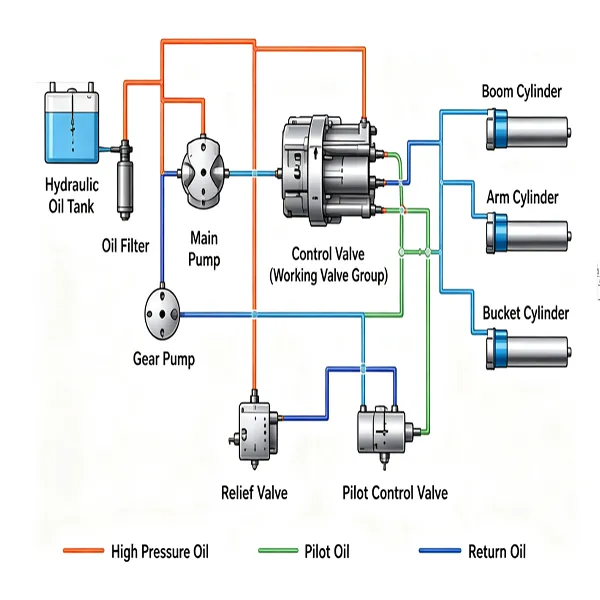


Komatsu PC200 hydraulic system troubleshooting requires a clear understanding of how the excavator’s hydraulic system operates. Common problems include slow or weak boom movement, slow swing, low hydraulic pressure, internal leakage, and hydraulic pump or control valve faults.
The hydraulic transmission systems on an excavator mainly include the pilot control hydraulic system, swing hydraulic system, travel hydraulic system, and work-equipment hydraulic system. These systems offer advantages such as compact structure, flexible operation, smooth running, and convenient control. Hydraulic oil serves as the medium for transmitting power. As internal components wear, leakage may occur, often accompanied by faults such as overheating and weak operation.
Hydraulic transmission faults can occur suddenly and may be difficult to detect. Because many components are involved, diagnosis and troubleshooting can be challenging. Therefore, when servicing a hydraulic system, the technician must understand its operating principles and correctly analyze the cause of the fault in order to ensure repair quality. Using common faults on Komatsu PC200 excavators as examples, this article introduces the operating principles of hydraulic transmission and explains how to diagnose and eliminate common hydraulic faults.
1. Operating Principle of the PC200 Excavator Hydraulic System
The hydraulic system of the PC200 excavator consists of a number of basic and auxiliary circuits, including the working circuit, pressure-limiting circuit, unloading circuit, cushioning circuit, throttle speed-control and throttle speed-limiting circuits, travel speed-limiting circuit, and pilot-valve control circuit. Its main components include the main working pump, charge pump, pilot control valve, distribution valve, relief valve, boom cylinder, arm cylinder, bucket cylinder, hydraulic tank, and related piping.
During operation, the hydraulic system of the PC200 excavator draws hydraulic oil from the bottom of the tank through an oil filter into the working pump. The pressurized hydraulic oil output from the pump then enters a set of parallel distribution valves. Actions are achieved via a handle → pilot valve → working valve assembly. The system’s total pressure is limited by a main safety valve on the main oil line, while the safety valves in each working oil circuit provide overload protection and oil replenishment for their respective circuits.
2. Diagnosis and Troubleshooting of PC200 Excavator Hydraulic System Faults
The hydraulic system of the PC200 excavator is set to a pressure of 30 MPa. A pressure below this value is considered low system pressure. Hydraulic system faults mainly appear in two forms: slow and weak boom lifting, and slow and weak swing operation. The primary cause of both faults is low working oil pressure, while the main causes of low pressure are blockage and leakage.
Clear oil passages and good sealing are essential for normal hydraulic system operation. Blockage and leakage are the most common hydraulic transmission faults, so troubleshooting generally begins with the hydraulic oil circuits. The following sections describe the diagnosis and troubleshooting methods for different hydraulic system symptoms.
2.1 Komatsu PC200 Boom Lifts Slowly or Feels Weak Other Functions Operate Normally
Fault diagnosis: If only the boom lifts slowly and weakly while bucket tilting/curling operates normally, this indicates that the main working pump and main relief valve are functioning properly and can provide sufficient pressure to the entire system. It also indicates that the pump inlet piping and filter, as well as the oil level and oil condition in the tank, are satisfactory. In this case, only the boom spool valve, boom cylinder, boom hydraulic lines, and related seals need to be checked.
(1). Check for Blockage in the Hydraulic Circuit
First perform routine servicing. Remove the hydraulic lines, then remove the boom spool valve body, spool, and related parts for cleaning. Thoroughly clean the oil passages and blow them through and dry them with compressed air.
(2).Check for Hydraulic Circuit Leakage
- Hydraulic system leakage generally develops after the machine has been in service for some time. Visible causes commonly include failed, damaged, or extruded seals, or scratched sealing surfaces. Major causes include contaminated oil, improper sealing-surface roughness, defective seal grooves, loose pipe fittings, increased clearance between mating components, excessively high oil temperature, deteriorated seals, or improper assembly. Leakage can be divided into internal leakage and external leakage; in practice, faults are usually caused mainly by internal leakage.
(3) Handling Internal Leakage Faults
Internal leakage in this section mainly occurs in the boom spool valve and the hydraulic cylinder. Because internal leakage occurs inside the valve body and cylinder, it is difficult to inspect directly. However, several auxiliary methods can be used to determine whether leakage is present.
(4) Inspection of the Boom Cylinder
After fully retracting the boom-cylinder piston, disconnect the hose from the cap-end chamber and continue supplying oil to the rod-side chamber. If a large amount of working oil flows out of the cap-end hose port, the hydraulic cylinder has internal leakage. Another method is to fully load the bucket, raise the boom to its upper limit, place the boom control lever in neutral, shut off the engine, and observe the boom settling speed. Then move the boom control lever to the raise position. If the boom settles noticeably faster, the internal leakage is in the hydraulic cylinder. If the settling speed changes very little, the internal leakage is in the boom spool valve.
(5) Inspection of the Boom Spool Valve
Leakage at the boom spool valve is mainly caused by excessive clearance between the spool and valve body, a damaged pressure-regulating spring, or damaged seals inside the valve. Check the fit clearance between the spool and valve body, inspect the pressure spring, and check whether any internal valve seals are damaged.
Troubleshooting Method:
If the cylinder internal-leakage test result exceeds the specified limit, disassemble the cylinder for further inspection. Replace damaged seals; if the cylinder wall is severely scored, replace the damaged component. If the boom valve is severely worn, replace it.
2.2 Boom Operates Normally, but Komatsu PC200 Arm Moves Slowly or Has Low Power
Fault Diagnosis:
If the boom operates normally but the arm is slow and weak, this indicates that the main working pump and main relief valve are operating normally. It also indicates that the pump inlet piping and filter, together with the oil level and oil condition in the tank, are satisfactory. In this case, focus on checking the arm working spool valve, relief valve, and related seals.
Troubleshooting Method:
The diagnosis and troubleshooting methods for hydraulic transmission faults are generally similar. The fault-handling methods for the arm section are basically the same as those for the boom section. Therefore, faults affecting arm operation can be handled by referring to the procedure in Section 2.1 for boom faults.
2.3 Slow and Weak Boom Lifting; Slow and Weak Swing Operation
Fault Diagnosis:
When both the boom and swing functions of the work-equipment hydraulic system operate abnormally, there are many possible causes. In addition to the faults described above, the problem may also be related to the main relief valve, hydraulic pump, filter, hydraulic oil, or faults in the inlet and return passages of the distribution valve. Because many points are involved, inspection should proceed from easy to difficult and begin with the key items. Start with the most obvious checks: verify that the tank contains enough oil, and inspect the hydraulic oil for cleanliness, color, viscosity, consistency, and odor.
When hydraulic oil flows from the high-pressure side to the low-pressure side without performing mechanical work, heat is generated within the hydraulic system. Excessively high hydraulic oil temperature causes seals to deteriorate and the oil to oxidize and fail. It can also cause corrosion and deposit formation, which may block damping orifices and accelerate valve wear. Excessive temperature may even cause valves or pumps to seize. Any such problems should be corrected first, followed by inspection of several key areas. Statistically, it is relatively unlikely for the boom spool valve and swing spool valve to fail at the same time, or for internal leakage to occur simultaneously in the boom cylinder and swing cylinder.
Therefore, system pressure should be tested first. To test system pressure, install a pressure gauge with a 40 MPa range at the pressure test port. Run the engine at rated speed and raise the boom to its highest position. The gauge will then indicate the maximum pressure, which should read 27-28 MPa.
Troubleshooting Method:
If system pressure is low, analyze and troubleshoot the following areas:
(1) Internal leakage in the distribution valve: The main causes of internal leakage in the distribution valve include a stuck main spool in the main relief valve, excessive clearance between the spool and valve body, a damaged pressure-regulating spring, damaged internal seals, or casting porosity in the valve body. Disassemble and inspect the poppet of the main relief valve for sticking. Check the clearance between the spool and valve body; the normal fit clearance should be 0.005-0.025 mm, with a service limit of 0.04 mm. Check the clearance between the main spool and main valve sleeve; the normal standard clearance is 0.010-0.018 mm, with a service limit of 0.03 mm. Also inspect the pressure spring and internal valve seals for damage.
(2) Internal leakage in the main working pump: Pump internal leakage is indicated by excessive noise during operation, with the noise increasing as engine speed rises. A large amount of copper debris may also be visible in the filter. Disassemble and inspect the pump. Repair or replace it if damage is found.
(3) After the overall system-pressure problem has been checked and corrected, if operation is still abnormal, troubleshoot the boom and bucket sections separately according to Sections 2.1 and 2.2.
(4) If all of the above checks are normal, measure the pressure in the corresponding working circuits. When measured with a pressure gauge under the “swing” and “boom raise” operating conditions, the working-circuit pressure may be only 10 MPa and the pilot-control system pressure only 0.5 MPa (normal value: 2.8 MPa).
While the working pressure and pilot-control pressure under other operating conditions remain normal. Careful analysis of the hydraulic schematic shows that the pilot circuit for swing-control priority and the pilot circuit for boom-control priority can communicate with the circuits of the left travel control valve and the straight-travel valve. It can therefore be preliminarily judged that high-pressure oil in the “left travel control valve” may be acting on the “straight-travel shuttle valve,” causing the spool of the “straight-travel shuttle valve” to move away from its neutral position. As a result, the pilot-control circuits for “swing” and “boom raise/lower” are bypassed and depressurized after passing through the “shuttle valve” and “straight-travel valve.”
If lightly operating the “left travel” control lever makes both swing and boom raise noticeably faster, the spring and oil seal at the end of the “left travel control valve” can be suspected. After removing the left travel control valve, the oil seal and spring were found to be clearly damaged. Replacing them with a new spring and oil seal eliminated the fault.
3. Precautions When Servicing an Excavator Hydraulic System
- Hydraulic components must be thoroughly cleaned, and all oil passages must be clear before assembly.
- Do not use contaminated hydraulic oil or low-quality seals.
- Components must be assembled correctly. For example, the opening direction of a Y-type seal must not be reversed, and hydraulic lines must not be connected incorrectly.
Do not adjust the displacement of the main working pump or the relief valves before fully understanding the required settings. Setting them too high may damage hydraulic components, while setting them too low may cause slow, weak, or completely inoperative machine functions.
In summary, when a hydraulic system fault occurs, do not make adjustments blindly. Analyze and solve the problem in the order of “easy before difficult, external before internal, and key items before general items.” Normally, first check for external leakage, then check oil level and oil condition, followed by possible blockages. For faults caused by internal wear of components, first understand the operating principle and then carry out targeted inspections. A deeper understanding and better command of the hydraulic system, together with continued improvement in technical and practical skills, are essential for solving the major problems faced by hydraulic equipment users and for managing the hydraulic system effectively.